Version 8.1 - Migration guide for users
Summary
These are the most important changes and additions in this release :
- This is an important version for performance improvements on large projects and projects with many sheets :
The 3D drawing will open faster when there are many parts or sheets in the drawing while the sheets manager is open.
The sheets manager will respond much faster when there are many sheets in the drawing.
Generation speed of GA views has been greatly improved for large views that contain many objects, or blocks and Xrefs with many objects inside. - Additional filtering options for general arrangement drawings using object filters on 2D views, cameras, and sheets. This allows simpler control of what to show during camera or view creation.
- Views with new purposes were added by using new view capabilities (focus views, colored views and incremental views)
- Create grating and floorplates based on any free-form plate, previously this was restricted to strips/panels. Adding grating or floor data to a plate has the advantage that the plate can have any size as opposed to standard sized strip-based grating panels.
- Custom grating bar sections are now supported in grating objects, for example to draw detailed pultruded grating. Some additional settings allow better control of load bar and cross bar offsets.
- There are many more capabilities for the level of detail in which grating bars, surface treatments and 3D model hatches are shown on 2D views
- Many new connections and structural macros were added.
- Unfolding of a structure or an entire assembly is now possible if BricsCAD Mechanical is installed. This tool allows us to greatly simplify the 3D modeling of folded parts because the tool will draw bends and recesses automatically.
- Quick select improvements : It is now possible to filter objects inside any command when an object selection prompt is already active. This adds a powerful filtering tool to all AutoCAD, BricsCAD, and Parabuild commands and there does not exist any equivalent tool in AutoCAD nor BricsCAD (when a command is active)
- Layout viewports can now be shown on Parabuild sheets. There is a new checkbox in the printing dialog to make the layout display correctly during the print process.
- Support for AutoCAD 2025 was added
- Many other new features
Object filters for cameras, views and sheets
Object filters for cameras
It is now possible to add include and exclude filters to cameras, camera-specific filtering on any combination of object properties is now possible. Previously it was only possible to manually select specific objects to include or exclude. Camera based filtering is convenient for example when multiple views will be created from a camera and the filters should be applied to all those views.

Camera settings can now also be saved and loaded to speed up creation of frequently occurring camera types.
Object filters for views and sheets
When creating a new view or a new sheet, additional filters can be specified before creation of the view or sheet, and default filters can be configured in Parabuild output settings for each general arrangement settings entry.
Sheet filters will apply to all views on the sheet even if views are added to the sheet later on. Sheets that show only a specific phase on all views of the sheet are a good use case example for sheet filters.
View filters are applied to the new views as they are created. View filters are an ideal choice if different filtering is done for each view on a sheet. An example could be a sheet that shows multiple phases or sequences on different views on the same sheet.

After creation view filters can still be modified with this view property :


After creation sheet filters can still be modified here in the sheets manager :


Note: if there are object types that should be shown a specific way in all views of a specific type, this can be pre-configured and saved in the View Appearance settings of that view type instead. Manual changes afterwards to camera, view or sheet filters is not needed in that scenario. Examples of this could be suppressed inserted plans, piping, furniture, ... Another example are the new view types explained below.
Views with new purposes by using new view capabilities
A simple filter applied to the view such as filtering for a specific phase number can now be used as a property inside other filters that query the view.
Filtered objects can also be brought back in the view, with a modified appearance. In practice this means that you can control the appearance and annotations of objects in the view based on what was filtered.
In the below examples the new view appearance capabilities are demonstrated with the object override filters.
Note that all the following view styles can be used with any type of camera, so you can use them with isometric views, section views, plan views, detail views or other box-limited views, etc...
A few new default view appearance settings entries with specific purposes demonstrate this new system :
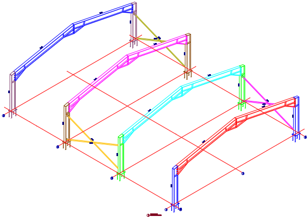
Focus views
Example of a view on which the objects of a certain sequence are shown normally and annotated. The view was filtered on that specific sequence, and the view appearance settings were set to draw all other parts greyed without annotations.
Incremental views
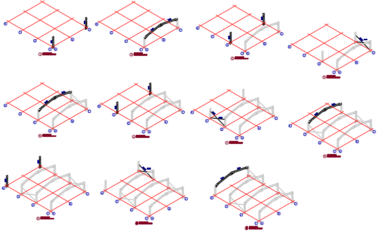
Example of views that incrementally grow based on the sequence : each view was filtered on a specific sequence, and objects matching that sequence get regular appearance and an annotation. Objects that have a lower sequence were made grey. Objects that have a higher sequence are not shown. All of these views are drawn with the same settings, they only vary in the chosen sequence at view creation.
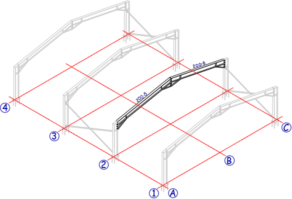
Assembly occurrence views
Example of an assembly occurrence view on an assembly drawing sheet, highlighting all occurrences of that assembly in the model. The view was filtered on that specific assembly number, and the view appearance settings were set to draw all other parts greyed.
These views can be created easily with these new default Parabuild GA settings :

If you do not have these settings entries that may be because you are using settings that were generated by an older version. You could reset all of your settings to the defaults, but if you prefer to keep your current settings then read the instructions on how to Import part of the default settings.
You will have to introduce settings entries on the GA drawings tab as well as on the View arrangements and View appearances tabs.
The above list may be much shorter when you use the tool to draw a new GA view.
That is because the full list of available GA views is filtered based on the camera that you selected. Only the GA views that make sense for the camera's direction are displayed.
Elevation views, plan views, and isometric view directions can be concluded from the camera's direction and that is how the GA presets are filtered.
But you can remove the GA preset reduction by enabling the Show all GA settings : 
Other view configurations are possible too, either by filtering on other or more properties, or by using other appearance settings.
How views like this can be configured is explained below. To create your own versions of these settings, it might be simplest to adapt an existing one to your preferences.
Focus on phase or sequence
Focus views are useful for highlighting specific parts of the model, such as a specific phase, sequence, material, or any other property or combination of properties. Default Focus views in Parabuild can be created by choosing the "Phase Focus" or "Sequence Focus" settings, and filtering the view for a specific phase or sequence.
Without further object overrides, such a filter would hide all the objects that do not match the view filter. However focus view settings have object overrides that re-introduce filtered objects back into the view, while assigning them a grey color. The below settings show a Phase-based example.
Setting the view filter to a particular phase or sequence is done during creation of the view.
Underneath the view filter setting the object filter is shown. Press Edit Local to change the property value :

Object overrides for the focus views can be found here : 
The following override for re-introducing filtered objects was added here :

Explanation for the settings in this override:
Local filter - This filter was set to apply only to Parabuild objects, but more important is the filter "View.Phase != Phase" : This means that the Phase of the object can not be the same as the phase of the view to pass this filter. The view phase is retrieved from the phase filter that was set for the view.
Applies to objects filtered out by the view or sheet - By toggling this on we signal that we are looking for objects that were filtered out of the view, so that we can bring them back and change their appearance with this override.
Enable skip display override - Enabling this checkbox together with the Skip display setting turned off makes sure that the objects will be drawn in the view
Enable color index override - Enabling this setting will assign the grey color number (9) to all the objects that are re-introduced back into the view
Incremental views
Incremental views are useful for showing erection stepwise based on sequence, phase, or other user chosen properties. In this example sequence that was filtered for is shown as regular geometry, and the earlier sequences are shown as greyed geometry. The parts of later sequences are skipped from the view.
The annotations are configured to automatically annotate only the focused parts and not the greyed parts.
All of these views started from the same GA settings (incremental), they only got a different view filter when the view was created:
These are 11 incremental views and each one was created separately using the same view settings, but applying a different sequence during creation of the view.
Incremental views are created one by one by choosing a different phase or sequence for each view.
Without further object overrides, such a filter would hide all the objects that do not match the view filter.
However incremental views have object overrides that re-introduce some of the filtered out objects back into the view, while assigning them a grey color. The below settings show a sequence based example.
Setting the view filter to a particular phase or sequence is done during creation of the view.
Underneath the view filter setting the object filter is shown. Press Edit Local to change the property value :

And the overrides for the incremental views can be found here : 
The following override for re-introducing filtered objects was added here :

Explanation for the settings in this override:
Local filter - This filter was set to apply only to Parabuild objects, but more important is the filter "View.Sequence > Sequence" : This means that the Sequence of the object needs to be smaller than the sequence of the view. The view sequence is retrieved from the sequence filter that was set for the view.
In other words, we are targeting parts that have a smaller sequence than the sequence of the view.
Applies to objects filtered out by the view or sheet - By toggling this on we signal that we are looking for objects that were filtered out of the view, so that we can bring them back and change their appearance in this override
Enable skip display override - Enabling this checkbox together with the Skip display setting disabled makes sure that the objects will be drawn in the view
Enable color index override - Enabling this setting will assign the grey color number (9) to all the objects that are re-introduced back into the view
Notice that we do not have settings that bring back parts with a sequence larger than the view sequence. This is what allows the incremental display style of successive views, which is the main difference with Focus views.
Occurrence focus view for assembly or GA sheets
This view solution is similar to focus on phase or sequence, but instead the focus is put on a certain assembly number.
An example assembly drawing with an isometric occurrences view added on top
This view can be added after an assembly sheet has been generated, for cases when the additional context could be useful to the shop floor.
It can also be useful on general arrangement sheets, for providing context during erection.
This is how to add this view to an existing sheet :
- Open an assembly drawing
- Right-click on a camera in the sheets manager, and click on Add to current sheet
- Choose the GA setting GA - Isometric View - Assembly Focus
- If the camera has a isometric viewing direction then choose the view Front. If the camera has a plan/elevation viewing direction then choose one of the Isometric views
- Note that the occurrence view only works properly if the assembly number is filtered on in the view's filter. When adding the assembly focus view on an existing assembly sheet then this filter is added automatically for you. Just click on Edit Local to change the assembly number if necessary :

Colored by phase or sequence
Colored views were already possible and can be configured in View Appearance settings by filtering by phase, sequence number or any other property, and then setting a color override.
Examples based on phase and sequence properties were now added to Parabuild default settings to show how this is done, changing the color and annotation based on the phase or sequence of each object.
For the colored sequences you can find the overrides here : 
The following settings were set here for each sequence :

Explanation for the settings in this override:
Local filter - This was set to the sequence number that is being overridden. The sequences from 1 through 40 were created here. If you use a different way of assigning names to the sequences then you will have to change all the sequence names here.
Enable color index override - Enabling this setting will assign the color number to all the objects that have the filtered sequence number or name
The object type that should be overridden for annotations - An override was enabled for assemblies and bolts
Enable annotation style override - The Pb Assembly Sequence style was chosen, so all objects with this sequence will get a sequence annotation
Enable annotation template override - This override was enabled and the template string is empty. This means that the template text that may have been set for this object is removed, ensuring that the Pb Assembly Sequence style's default template string will be used
As you can see there is an override needed for each sequence here. Each override contains the filter on the correct sequence number (or name) and then the color number for that sequence.
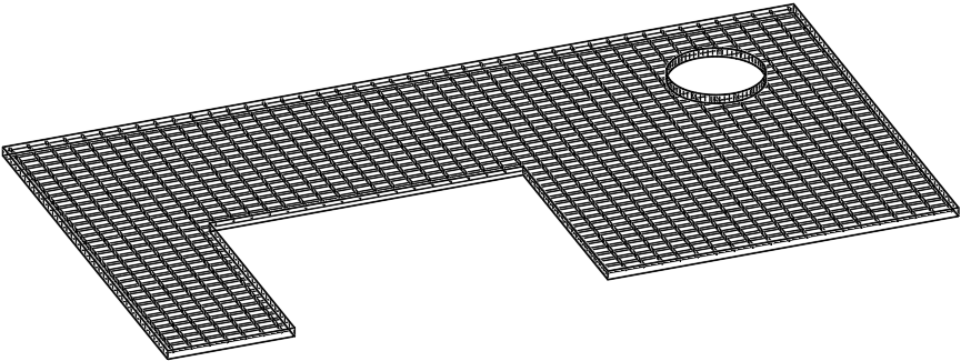
Add grating or floor plate data to any plate
Command - PrB_GratingOnPlate

This command creates grating and floorplates based on any plate, previously this was restricted to strips/panels. The grating or floor plate geometry will then always show on the plate in 3D or 2D views - if allowed by the appearance settings of the view.
The command accepts plates, polylines, circles and strips for the selection. The polylines, circles and strips will be converted to plates automatically.
The thickness of the plate will be adjusted automatically to match the thickness of the grating data.
Adding grating or floor data to a plate has the advantage that the plate can have any size or shape, whereas the strip-based grating or floor section tables have a limited set of grating widths and thicknesses to match standard sizes available from manufacturers.
Grating or floor plate data in the 3D model can now also be modified, added, or removed from the advanced properties of the plate.
Library grating or floor plate data is configured in and retrieved from grating section tables.
We can use the grating section tables with standard widths (the width will be ignored) or you can use one of the newly added section tables that were created specifically for plates.
Section tables for plate-based grating are the same as other grating section tables except for 3 things :
- They contain a new column "Plate Name Template", which allows you to influence the plate name. When you leave this field empty then the name of the grating plate will be the plate's sizes in combination with the grating's row entry name. It is allowed to use variables in this string such as %Name% which inserts the default name of a plate, containing general sizes of the plate.
- These tables contain the width column, but this column is ignored because the width is solely determined by the plate
- The weight per length column is also ignored because the weight is calculated based on the area of the plate
When using Parabuild to draw grating we can at any time choose whether the grating should be drawn fully detailed, approximated, or even just by a hatch or span symbol. This allows us to draw projects with large amounts of grating. If it starts to affect computer performance, then set the grating graphics to be approximated and turn it back on when it is time for checking or rendering.
The grating appearance can be modified per part in the properties, or globally in the views manager :


Modifying grating information of existing members and plates
The grating information can be modified in the advanced properties, which is accessible from the Properties panel.

The new advanced properties are clarified below :
Load/Cross bar remainder type - Choose how the bars are distributed over the plate's width or length.
|
|
|
The result when the cross bar remainder type is set to Centered |
The result when the cross bar remainder type is set to At start |
The result when the cross bar remainder type is set to At end |


Enable load/cross bar reference offset - This is the offset from the edge of the grating panel to the center of the bar
If the remainder type is set to centered then the reference offset is taken as an indication of a minimum offset.
If the edge distance is smaller than the reference distance, Parabuild will attempt to reduce the number of bars by one to increase the edge offset
If the remainder type is not set to centered: If remainder is "At start", this fixed offset will be "At end", and vice versa
No minimum or maximum is applied, so be careful as this can cause incomplete or cut grating at that side
Custom grating bar sections
It is now possible to use custom grating bar sections, for example to accurately portray pultruded grating. Custom sections will appear in both the 3D model, shop drawings and GA drawings, if configured that way in the view appearance settings.
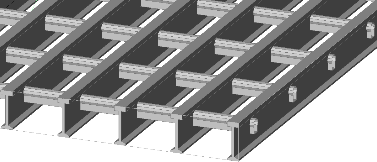
This is an example of a pultruded grating with a loadbar specified by section name, and a custom section for the crossbar specified by filename
Using section names or custom sections in grating tables
To use the new features we can add the new columns with the name LoadBar Section and Crossbar Section to the grating tables :

For the contents of these section fields we can choose one of the following :
- The name of a section that is defined in one of the Section tables
- The dwg file name of a Custom shape that is stored in the library
New section table for load bars
A new section type called I section with flexible input was specifically added for representing these grating load bars.
A new section table called Grating I Loadbars was added which uses this new section type :


Most columns speak for themselves, but there are some special cases that need further explanation :
- BottomFlangeWidth is to allow for a smaller bottom flange (the top flange has the width of the Width column)
- ThicknessInside means the thickness of the flange at the web
- ThicknessOutside means the thickness of the flange at the outer edge
Splitting ThicknessInside and ThicknessOutside allows for flanges that are sloped on the inside such as this example.
We will not be using this section table to draw profiles so therefore this section table is by default not enabled in the Draw Profiles selection dialog box.
But the section table needs to exist nonetheless so that the grating tables can access the loadbar data from here.
New offset columns for specifying loadbar and crossbar position
The example grating tables for molded and pultruded grating contain the 4 new columns :

The columns are further explained :
- LoadBar Remainder Type - In this column only 3 numbers are valid : 0 = centered, 1 = at start, and 2 = at end
- CrossBar Remainder Type - This is the same as the loadbar column
- LoadBar Reference Offset - This column should contain a distance by which the bar should be moved, on the opposite side of the remainder type
- CrossBar Reference Offset - This is the same as the loadbar column
New 2D view appearance capabilities for grating, surface treatments, hatches, and layer targeting
There are several new capabilities for the 2D view representation. Note that all of these appearance settings can be configured differently for part drawings, assembly drawings, plan views, elevation views, isometric views, section views, detail views, etc...
We will explain each new capability in detail below.
The new capabilities can be enabled or disabled in the fetch settings dialog box, which can be opened from here :

We will go into detail on each new or changed option in this dialog box :

Lines and curves - When enabled, lines and curves in the 3D model will be included in the view.
Polylines - When enabled, polylines in the 3D model will be included in the view
Points - When enabled, points in the 3D model will be included in the view
Block references - When enabled, block references in the 3D model will be included in the view
Modify layer states of view - To specify in advance which layers in the 3D model to be on or off for the view.
Any layers not listed here but that do exist in the 3D model will get the current layer on/off state from the 3D model at the time of view creation.
Add hatches from 3D drawing - When enabled, hatches in the 3D model will be included in the view. These hatches will also be clipped by the view. This concerns only hatches drawn in the 3D model and has no influence on the hatches that may be drawn by Parabuild for the representation of surface treatments and grating. Those are not separate objects but they are integrated inside plates and profiles, and are controlled using the settings below.
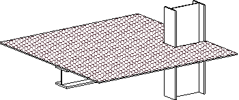
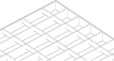
Hatch type for surface treatments - Surface treatments are different from outer surface hatches so take note not to confuse them. A surface treatment is usually activated on a surface of a part to indicate that that surface should be shown and treated differently from all the other surfaces of the object. An example is a raised pattern floor plate, which should have the raised pattern on the top face of the plate and this information will be used by the Parabuild numbering system and shown on 2D views.
This setting determines how the surface treatments of 3D objects should be shown in the 2D view.
The 3 possible options are shown here with result examples.
- Never : Surface treatments are never shown on the 2D view
|
|
A floor plate as drawn in the 3D model |
The result on the 2D view : the surface treatment is not drawn |


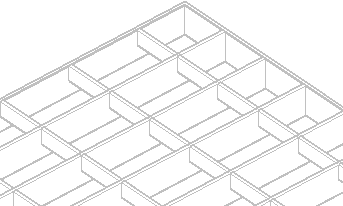
- Draw hatches on front of the object : When looking at front of the surface treatment then the treatment will be drawn. But looking from the back side of the surface treatment then the treatment will never be shown
|
|
|
The surface treatment of the floor plate is shown when looking at the front of the treatment |
The surface treatment of the floor plate when looking at the back of the treatment |
The surface treatment of the floor plate when looking at the back of the treatment with hidden lines active |


- Draw hatches on front and back of the object : The surface treatment will be shown when looking at the front and the back of the treatment. Note that for the back of the treatment to be shown hidden lines need to be activated as well, otherwise the back setting has no effect since the hatch will be hidden.
|
|
The surface treatment of the floor plate is shown when looking at the front of the treatment |
The surface treatment of the floor plate when looking at the back of the treatment. Hidden lines needs to be activated for this to have an effect |

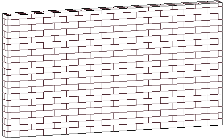
Hatch type for outer surface hatches - Outer surface hatches are different from surface treatments, so take note not to confuse them. The outer surface hatches are defined in the hatch settings on the general tab. We can assign an outer surface hatch to objects based on any filter. This setting works the same way as "Hatch type for surface treatments".
Unlike surface treatments however, outer surface hatches are added automatically on 2D views instead of specified in the 3D model. In addition to this setting in the view, this requires setting up your automatic hatches in the general tab of the Parabuild output settings. Filtering can be based on any combination of properties, for example allowing you to specify a hatch for all solids on a specific layer. Remember that a hatch is a planar object, so hatches will not be applied to curved surfaces.
In this practical example we added an outer surface hatch for all the objects that have the material Brick :


The necessary settings for the brick hatch on objects that have the Brick material are highlighted
And these are the results with or without the above hatch setting :
|
|
This is a wall object without any material assigned |
This is the wall object with the brick material assigned to it. Note that all visible external surfaces will get the same hatch pattern |

Hatches for sectioned views - Enable this to draw hatches whenever a part is clipped by the view's clipping faces. This requires setting up your automatic hatches in the general tab of the Parabuild output settings, similar to outer surface hatches.
Default sectioning hatch patter spacing, angle, scale, and pattern - Choose the default hatch configuration for sectioned objects. These hatch settings will only be used when there is no hatching configuration done for the 3D object. On the general tab the hatches are already configured for the most common materials, it is recommended to adapt those to your preferences.
- Grating display style - This will influence how grating is drawn in the 2D view. Parabuild settings of some view types have grating appearance set to lightweight types, such as hatched for large isometric views, and others set to full detailed grating for example in detail views. Be sure to adapt those settings to your preferences.
There are the following display styles to choose from : - None - The grating will not be drawn, only the outline of the plate will be visible with an optional span direction symbol.
- Simple hatch - The grating will be represented by a simple hatch : 1 line per bar
- Simple hatch see through - The grating will be represented by a simple hatch : 1 line per bar. Everything behind the grating plate is drawn as if the grating plate does not obscure anything behind it. If there are any edge bars, they are drawn in full.
- Real hatch - The grating will be represented by a hatch that shows 2 lines per bar.
- Real hatch see through - The grating will be represented by a hatch that shows 2 lines per bar. Everything behind the grating plate is drawn as if the grating plate does not obscure anything behind it.
- Continuous plates - In this style the grating bars are drawn, but they are colliding with each other. This causes less lines to be drawn and the bar intersections are not exactly drawn according to drafting rules. This makes the creation of views slower if there is a lot of grating, but is still faster than the 'Realistic' option.
- Realistic - In this style the grating bars are fully detailed with intersecting lines where bars cross each other. This will take the most time when creating views with a lot of grating.
Combining surface treatment on top of grating and sectioning of detailed grating representations are also supported for 2D views.
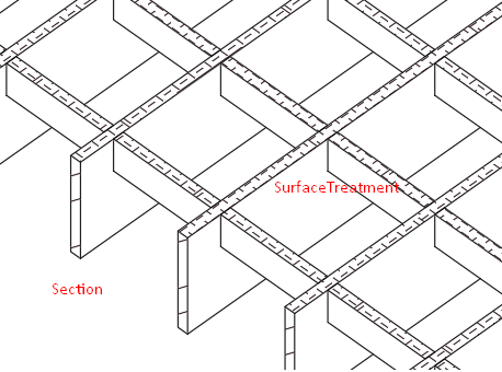
This is an example that combines some of the new 2D view capabilities : 1) Grating is drawn in full detail 2) The grating is clipped and the section hatches of the grating bars are drawn 3) The top surface has a surface treatment and only the top faces of the grating bars receive the surface treatment hatches in 2D views
New straight ladder on a model line
Command - PrB_Ladder


The new macro is explained in detail :
Straight ladder |
This macro was added to provide a new and easy way of inserting a ladder. |

New and revised stair macros
Command - PrB_Stair


The existing stair macro was revised and a new CIP version of the stair was added.
These macros are explained in detail :
Stair |
This macro is not new but has been revised entirely. Some of the new capabilities are :
|
CIP Stair |
This new macro draws Cast-in-place (CIP) steel treads instead of standard grating treads.
|


Platform and Crossover macros
Command - (Prb_MacroGroup "Misc Macros")


For now there are just a few macros available with this command : we can access a crossover macros and simple platform macros, both based on a line.
Some of these macros are base templates that can be used as a starting point for templates customized to your needs.

Each of these macros are explained in detail :
Platform |
This macro will draw a platform on a model line. The platform consists of 4 members that are not yet connected. The model line defines the position and length of the platform. The width and member sizes are variables in the macro.
The macro does not do a lot in this state.
If you want to make such variants of this macro then just open the macro dwg file in this folder, modify it and save it under a new name : |
Platform with grating |
This macro is exactly the same as the normal platform but it also has a single grating plate on top of the platform. |
Crossover model lines |
This macro expects a single model line to be selected, and this would be for the platform of a crossover. |
Crossover example |
This crossover example demonstrates how to combine multiple simple templates into potentially many variants and store them in your library for future use. This macro is a combination of the platform macro, the crossover model lines, the stair macros on model lines, and the railing macro.
If you plan on adding your own template variants, then save them in the Parabuild library, here: \Parabuild\Pb_Lib\Macros\ |
Circular plate with chamfer |
This macro will draw a circular plate (as a strip profile) that has a circular chamfer on one side. |


Boxed truss
Command - (Prb_MacroGroup "Vakwerk")


A new macro that draws a fully detailed boxed truss has been added to this command :
Boxed truss Angles |
This macro expects a single model line to be selected. It will draw 4 chords and then 4 arrays of braces between them. |

New composed members
Command - (Prb_MacroGroup "PEB Member")


2 new composed members were added to this command :
Channels back to back |
This macro expects a single model line to be selected. It will draw 2 channel profiles back to back on this model line. |
BOX Member |
This macro expects a single model line to be selected. The macro will draw 4 plates as strip profiles on this model line. |


Lifting lug and rebar macros
Command - Prb_StudsOnPlane


The new lifting lug and rebar macros can be found in the studs command because they use the same selection method : A planar surface needs to be selected, and the neighbouring faces are detected and used to position the macro.
These connections are explained in detail :
Lifting Lug |
This macro expects a planar surface to be selected. The macro will draw a lifting lug on this surface. |
Rebar C |
This macro expects a planar surface to be selected. The macro will draw an array of C rebars on this surface. |


Command - (Prb_MacroGroup "Versterkingen")


Different lifting lugs that are welded on their side face can be inserted using this command :
Lifting Lug for I / H / W member |
This macro expects a selection of a I / H / W member, and then a point. The point is used to position the lug on the length of the member. The lug penetrates through the top flange and touches one side of the web. |
Lifting lug for angle |
This macro expects a selection of a angle member, and then a point. The point is used to position the lug on the length of the member. The lug is attached to a leg of the angle. |


New Misc ending connections
Command - (Prb_MacroGroup "Misc end connections")


The following connections were added to this command for making them widely applicable.
The connections will ask a planar surface to connect to. You are free to select the surface of any profile or plate. This could also be the surface of any custom section shape.
The gusset plate connections are still experimental. Let us know what you think of them.
The new connections are explained in detail :
Purlin-Girt Bracket with 2 angles |
This macro will draw 2 angles under a C-shaped girt |
Small pentagon Gusset plate |
This macro will draw the small pentagon gusset plate against any surface |
Pentagon Gusset with force distribution |
This macro will draw the larger pentagon gusset plate against any surface |
Pentagon Gusset with force distribution 2 planes |
This macro will draw the large pentagon gusset plate against 2 surfaces. |
Rectangular Gusset plate |
This macro will draw a rectangular gusset plate against any surface |
Round rod plates |
This macro will draw 2 plates, one of which is welded to a round rod |
Hillside washer |
This macro draws a hillside washer object that is attached to a round rod. The plane that you select will receive a slothole so that the round rod can penetrate the surface and the hillside washer draw on the opposite side. |
Flangeplate & Weld improvement |
This connection combines a flange plate with the cutouts and backing bar for welding along the entire flange's depth |
Weld improvement arc |
This connection adds only the cutouts and backing bar for welding along the entire flange's depth. |
Weld improvement large |
This connection adds only the big cutouts and backing bar for welding along the entire flange's depth. |
Vent holes for RHS |
This connection adds 4 partial holes on the surface that you select You can optionally choose to draw 4 holes instead |
Vent holes for pipe |
This connection adds 4 partial holes on the surface that you select You can optionally choose to draw 4 holes instead |
Elbow vent holes |
This connection will draw a hole on the inside and outside of the elbow |
ClipAngle to plane |
The macro is available for I and C shapes. |
Skewed Cleat to plane |
The cleat is available in rounded and in non-rounded versions. The macro is available for I and C shapes. |


New endplate/footing connections
Command - (Prb_MacroGroup "Voetplaten")


The new connections are explained in detail :
Endplate chamfered to plane |
This endplate connection adds a chamfer to each corner of the endplate |
Endplate rounded to plane |
This endplate connection adds a fillet to each corner of the endplate |
Angle footing |
This macro adds an angle and a plate for an inclined channel member. The vertical position of the angle is always the world of the drawing. |
Angle footing to plane |
This macro adds an angle and a plate for an inclined channel member. The vertical position of the angle is prompted for with a surface selection. |


New connections for CNC lasered tubes
Command - (Prb_MacroGroup "Weld connections")


These new connections were created specifically for rectangular tubes and pipes that will be produced with a CNC laser.
Some of them will have inserts in the tubes so that they will fit instantly. They are perfect for assembling and welding in the shop without the need to measure and no mistakes can be made!
Each of these new connections are explained in detail :
Pipes connected hollow |
This connection cuts open the vertical pipe, and the horizontal pipe fits in perfectly. The connection will also work in inclined situations. |
Pipe to Pipe with inserts |
This connection does not completely open the vertical pipe but only adds an optional vent hole to it. The connection will also work in inclined situations. |
T connection with inserts |
This connection adds inserts to the horizontal tube so that it can fit in the same-sized holes in the vertical tube. The connection will also work in inclined situations. |
Miter with inserts |
This connection draws a miter to connect the tubes, but it also adds inserts to the tube that was selected first so that it can fit in the same-sized holes in the other tube. |


New beam to beam connections
Command - (Prb_MacroGroup "Ligger tegen ligger")


The new connections are explained in detail :
Bolted Stiffener & Weld improvement |
This macro combines the pre-existing bolted stiffener with the weld improvement cuts and backing bar. |
Bolted Stiffener for channels |
This macro already existed before, but now variations have been added for using it on 1 or more channels. |


Corner braces
Command - (Prb_MacroGroup "Hoek")


The new corner brace connections add a single member in the corner of 2 members that are selected.
The new connections are explained in detail :
Corner brace for I/H/W members |
The corner brace is not connected to the base members. You should still connect them by using other connections after inserting this connection. |
Corner brace for pipes |
The corner brace is connected to the base members using a cutout but this connection can still be replaced with another type afterwards. |


New girt connections
Command - (Prb_MacroGroup "Gordinghaken")


The new connections are explained in detail :
Girt support with plate |
This macro adds a plate underneath a wooden girt, and the girt will stop at the flange of a profile. |
Girt support with plate |
This macro adds a plate underneath a wooden girt, when the girt needs to extend to the web of the column. |


New purlin connection
Command - (Prb_MacroGroup "Gording bovenop ligger")


The new connection is explained in detail :
ClipAngle |
This connection adds a clipangle to attach a RHS profile and drill it through-and-through |

New handrail connection
Command - (Prb_MacroGroup "Handgreep")


The new connection is explained in detail :
Handrail offset from post |
This connection will add a part underneath a handrail that connects it to a post |

New splice connections
Command - (Prb_MacroGroup "Splits")


The new connections are explained in detail :
Splice & Weld improvement |
This connection combines splice plates with the cutouts and backing bar for welding along the entire flange's depth |
Splice-lock |
This connection will draw a connector between 2 coincident RHS members. |


New brace center connection
Command - (Prb_MacroGroup "Schetsplaat 3 basis")

The new connection is explained in detail :
Circular Plate |
This connection will draw a circular plate that connects 3 angles of a 3-angle brace. |

Railing pickets and stiffener for BOX member
Command - PrB_DrawMacroFromGroup


The following macros do not have their own icon because they require a selection of 4 members and they could not be placed together with another group that would make sense.
After starting the command you should choose the group Misc 4 bases :

The new macros are explained in detail :
Railing pickets |
This connection will add an array of pickets for a railing.
This macro works on RHS rails and posts or Pipe rails and posts. |
Stiffener for BOX |
This connection adds a stiffener inside a BOX member. The plates of the BOX members should be selected in a circular order. |


Unfolding structures and assemblies with automatic sheet metal healing
When combined with BricsCAD Mechanical, this tool allows us to greatly simplify the 3D modeling of folded parts. We can just draw rectangular plates and we only need to make sure the plates are touching where we want the bends to be created.
This is an example to demonstrate the purpose of the tool :
|
|
This is an assembly composed of 4 separate plates that are added to the same assembly. The bends will only be created where the plates touch each other with faces. These 4 plates could also be combined into a Structure to achieve the same result. |
This is the resulting dxf file when the tool is run on the assembly. The bends and the necessary recesses were created automatically. |

Automatically combining and unfolding multiple parts like this is only possible when BricsCAD Mechanical is installed and licensed. For regular unfolding of bent strips and cold rolled sections, BricsCAD Mechanical is not needed.
This tool is available from the properties panel.
For an assembly you can select any part in the assembly to access the tool :
For a structure this property was added to access the tool :
The tool generates a dxf file that is stored under the 3D model's folder that carries the part number of the structure or the assembly number.
To achieve this, the tool merges all of the parts in the assembly or inside the structure into a single solid. Then it performs "Sheet metal healing" on this solid so that bends and recesses are automatically created and it becomes an unfoldable sheet metal part. Then the unfold is run on that healed part.
It may often be preferred to merge the parts together into a single structure and then unfold that structure, because a structure is a single part which has just 1 part number, and it can still be welded to an assembly.
It is possible to create a structure of several parts using the command Create Structure
BricsCAD mechanical is used by this tool to do the healing and unfolding.
Show Layout viewports on Parabuild sheets
In order to use this feature we can simply create new viewports using AutoCAD/BricsCAD commands to add them on the Parabuild sheets.
The layouts will display correctly on screen.
But in order for these viewports to display correctly when printing or writing a PDF of the sheet, we need to activate the Edit mode checkbox during the print command :

Other changes and additions
- The stair on a line macro has been updated to support the following new capabilities :
- The stringers can now be replaced with any other profile shape without this breaking the macros
- The locations of the entire stair relative to the model line can now be changed to : Left / Middle / Right alignment
- The top and bottom treads can now be enabled or disabled with a checkbox
- The cranked stringer additions at the top and bottom can be enabled or disabled, this is no longer required as a separate macro
- More information is shown such as the Tread going depth
- A new variant for the stair on a line macro was created, namely the CIP stair with Z-pan treads
- A new platform macro was added which can be inserted on a simple model line
- A crossover macro which can be inserted on a simple model line was added to the library. It includes a bare-bones macro that only draws the model lines. On this bare-bones macro custom crossover macros can be created with ease with the help of existing platform, stair, and railing macros.
- Other new macros are the a Ladder on a model line, Boxed truss, more Composed members such as BOX member, Girt connections, Beam to beam connections, Railing pickets, Splice connections, Corner braces, Vent holes, Connections for CNC lasered tubes, Lifting lugs, and Rebars
- New default GA view settings with grey color behavior for existing parts and blocks was added
- When creating new GA views the proposed settings are now filtered based on the camera's properties, size and rotation. The filters that are used for this can be changed in your general GA settings.
- A new bill that lists all sheets in the project can now be introduced from the standard settings
- A filter for the profile length optimizer command was added
- A new command Cut to planar surface was added
- A new command for changing the field hole status of a hole in absence of a bolt
- New global settings :
- Control the behaviour of the automatic creation or expansion of section tables when Parabuild drawings are opened and the sections do not exist in the local library
- It is now possible to deactivate the automatic conversion of Linear solids to Parabuild profiles (BricsCAD BIM)
- When you use the explode command on Parabuild objects then they will be converted into 3D Solids. This new behavior can be disabled in the Global settings
- The default precision of plates and members can now be modified
- Each level now has a new description property
- New bill and annotation properties were added
- 3D Solids will now be sectioned and hatched correctly when they are clipped by 2D views
- A change was applied to the grids command : if the dimension style PrB_GridDims exists then the dimensions drawn by this command will get that dimension style assigned
- When refreshing a GA view, annotations and dimensions will adapt better to changes of the view.
- When refreshing a GA view that has shortening enabled then the view could increase or decrease in size even when the model hasn't changed. This was fixed.
- Each sheet has a filter option in its properties. This will now also work properly on GA drawings. This option will filter all views and all bills on the sheet.
- Some stability issues were fixed
- When a very long path and filename was used then the generation of excel files could cause a fatal error. This was fixed.
New default GA view settings with grey color behavior
There were new default GA/workshop settings entries added for various new features, and to improve the out-of-the-box Parabuild settings.
In addition, new view appearance entries will by default :
- Make grey all objects that are on a layer name that starts with "Pb_Existing"
- Make grey all objects that are set to the structural types "Existing object", "Existing Steel", or "Existing Concrete"
- Make grey all objects that reside inside a block reference or an xref
- Entirely skip objects that are on a layer name that starts with "Pb_Helper"
- These defaults can easily be adapted to fit your own layer and object naming schemes, and your own color preferences. To adjust these settings, press the Object settings overrides button for the correct view style on the on the View appearances tab
If you are using settings saved before this update, then you will not have these new default settings for general arrangement drawings.
However you could introduce them into your existing settings by using the + button on the relevant tab of the Document generation Settings dialog box.
Note that view appearance settings like the grey coloring mentioned above are stored on the View Appearances tab so to introduce the new default GA view appearances, press the + button on that tab.

More GA view defaults, but filtered
With all newly added default settings, the number of options presented when creating new views had to be reduced.
The object filter on the GA drawings tab is now used to filter the list of view settings presented during when creating views.
This means when creating views using an isometric camera, isometric settings will be in the list.
When creation views for a detail camera, only detail view settings will be in the list.
For comparison, here is a complete unfiltered list of default settings:

However when creating a general isometric view the drafter gets this filtered list:

And for a connection detail the default list is filtered like this :

To achieve these filtered lists the properties, orientations and sizes of the cameras can be filtered on in GA drawing settings:

It is also easy to remove the GA types you will not use by pressing the  button after selecting them.
This will also help with a smoother detailing process.
New filter for the profile length optimizer command
The command now has 2 filter options :

The regular quick-filter is for filtering out parts that should not be processed by this command at all : not by the Not taken from stock bill and also not by the optimizer itself.
The optimize filter is for filtering out parts that should be listed in the Not taken from stock bill, but should not be processed by the length optimizer. An example where this would be useful is for off-the-shelf parts that do not need to be cut from stock lengths.
Quickly add a cut to any surface
A new command Cut to planar surface was added

This command allows us to quickly extend or shorten a profile against any planar surface. The longest side of the profile will be kept.
The capability was already available from the Add cut to macro command, this is simply a faster way to access this flexible tool.
Enable or disable field hole property
A new command PrB_ChangeFieldHole was added. It allows us to change the field hole property of a hole in absence of a bolt.

- The quick filter selection tool will now work during active commands that prompt for an object selection. Before, this tool only worked outside of commands.
This adds a powerful filtering tool to all AutoCAD, BricsCAD, and Parabuild commands and we are not aware of an equivalent tool in AutoCAD nor BricsCAD that functions when a command is active - You can now use quickselect to find specific annotations on sheets
For example, we can use a wildcard to find all annotations with a label that start with "300" :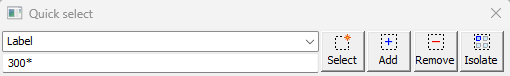
- If you are getting a warning that some annotations are invalid, you can find them on a sheet with this :

- You can also use quick select to find the shop bolts that are attached to more than 1 assembly. The filter that you can use for this inside quick select is invalid_shop_bolt
New Description property for levels
As you may know already, the level name can't contain spaces or any special characters. It can only contain letters and digits.
The limitation is there because the level name is used in equations to make it possible to make the level heights dependent on each other.
To overcome this limitation, a new property called Description was added to the levels :

The following new properties can be used in annotations of plan views to show the level description :
%ClosestLevelDescription% - This will show the description of the level that is closest to the part (beam) or the view's camera center
%StartLevelDescription% - This will show the description of the level that is located at the start of the annotated part (column)
%EndLevelDescription% - This will show the description of the level that is located at the end of the annotated part (column)
Please read the Note about special annotations for grids and levels
New bill columns and annotation properties were added
The following columns can be used in annotations and bills :
- PbColBoltAllPartNumbers : Lists all of the part numbers in use by the bolt assembly
- PbColBoltAllRingNumbers : Lists all of the washer and nut numbers in use by the bolt assembly
- PbColBoltAllPartNames : Lists all of the part names in use by the bolt assembly
- PbColBoltAllRingNames : Lists all of the washer and nut names in use by the bolt assembly
- PbColBoltAllPartStandards : Lists all of the part standards in use by the bolt assembly
- PbColBoltAllRingStandards : Lists all of the washer and nut standards in use by the bolt assembly
- PbColBoltAllPartTypes : Lists all of the part types in use by the bolt assembly
- PbColBoltAllRingTypes : Lists all of the washer and nut types in use by the bolt assembly
- PbColUnitNetWeight : Net weight
- PbColUnitGrossWeight : Gross weight
- PbColNetVolume : Net volume
- PbColNetPaintSurface : Net paint surface
- PbColMarkNetWeight : Net weight of assembly
- PbColMarkGrossWeight : Gross weight of assembly
- PbColMarkNetPaintSurface : Net paint surface of assembly
- PbColMarkNetVolume : Net volume of assembly
New generic properties
These can be used in annotations and filters, but not directly as bill columns.
- CameraName : Name of the camera (retrieved direct from camera or from view if there is a camera linked to the view)
- CameraIsBox : Returns 1 when the camera has box clipping enabled
- CameraIsSection : Returns 1 when the camera has front/back clipping enabled
- CameraDrawingSettingsName : Returns the default General Arrangement settings name that should be used when a new view is created starting from this camera
- CameraBoxSize : Returns the maximum size of the camera's box (1,000,000 if not a box camera)
- CameraIsUnlimited : Returns 1 when the camera does not have any clipping enabled
- IsCamera : Returns 1 when the object is a camera
- IsView : Returns 1 when the object is a view
- IsAnnotation : Returns 1 when the object is an annotation
- IsInvalidAnnotation : Returns 1 when the contents of the annotation could not be computed
- IsUnconnectedAnnotation : Returns 1 when the annotation is not connected to a view or part
New annotation properties
These properties will only work in annotation objects
- NumPartsInLabelGroup and NumAssembliesInLabelGroup : This will list the number of parts or assemblies that are to be produced within the confinement of the shop drawing or GA view. (for example '4x')
- NumPartsInLabelGroup2 and NumAssembliesInLabelGroup2 : These do the same but they will not display the count 'x1' when there is just 1 part
- ClosestLevelDescription : This will show the description of the level that is closest to the part (beam) or the view's camera center
- StartLevelDescription : This will show the description of the level that is located at the start of the annotated part (column)
- EndLevelDescription This will show the description of the level that is located at the end of the annotated part (column)
Note about special annotations for grids and levels
Some annotation properties will require Parabuild to search for a level or a grid, be that the closest one or at the start or at the end of an object.
Examples of these annotations are :
%ClosestGrid%, %ClosestLevelDescription%, %StartLevelDescription%, etc...
By default Parabuild will search the level or grid near the annotated part.
If this is not the desire but instead the level or grid needs to be searched for near the camera of the view, then "Camera." should be added to the annotation's template text like this :
%Camera.ClosestGrid%, %Camera.ClosestLevelDescription%, ...