View
The View object type is used in workshop drawings and on GA plans for showing a 2D representation of the 3D model or a part of it.
A view is a collection of 2D lines that are connected to their 3D model counterparts.
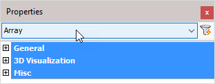
The view has the following headings :

General: Is common to all object types, and covers general AutoCAD and BricsCAD settings, including: Color / Layer / Linetype / Linetype scale / Plot style / Lineweight / Transparency / Hyperlink / Handle /
3D Visualization: Is also common to all object types and includes: Material.
The material that is referred to here is only the visual representation material. For changing the actual material of parts, see the Additional Data section of plates, profiles or structures.
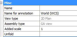
Misc

Name - The name view for description purpose
Name for annotation - The short name of the view, as it will be shown in annotations
View type - The main purpose of this type is for Parabuild so that it know whether this is a side view, an endplate view or something else
Assembly type - This relates more to the type of sheet on which the view is located (plate, member, assembly or GA)
Added scale - This scaling property is used to enlarge or shrink the view relative to the sheet scale. The sheet scale is always 0. Setting this to smaller than 1 will shrink the view. Setting it to larger than 1 will enlarge the view.
Dimensions and annotations that are connected to the view will be adapted but not scaled.
Unfold - Clicking on this button will generate an unfold of the part that is displayed by the view.
This button will only work on supported plates/strips. It is supposed to be used on the views of workshop drawings.
This option currently only works when Parabuild is run inside BricsCAD Mechanical.
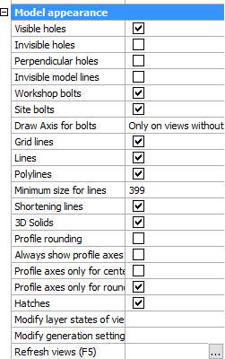
Model appearance

Practically all of the properties in this section are already explained in the topic.
But these 3 properties do need some more explanation :
Modify layer states of view - This button will open up a dialog where you can disable or enable layers. The 3D objects that are on the enabled layers will be shown in the view. All the other 3D objects will be ignored.
Modify generation settings - This is a link to the Modify view Settings dialog of this view
Refresh views - This will refresh this view only. See note.
Note!
After applying a change to any of the properties in the Model appearance section, you will need to refresh the view in order to see the changes on the view.
You can refresh views with any of these 3 methods :
- The function key <F5> will refresh all the sheets that are currently visible on your screen
- The refresh views button of the view itself
- You can right-click on a sheet in the sheets manager to refresh all the views on the sheet
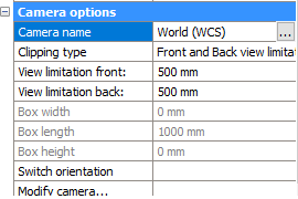
Camera options

Camera name - Shows the camera name to which this view is currently connected.
Use the button to link the view to a different camera. This can be useful when a view has lost its link to a camera after a delete or a copy/paste operation.
All the other options here refer to the linked camera.
Changing an option here will change the camera to which the view is linked
All of these properties are already explained in the camera topic.
