Various commands without icons
The commands listed below do not have an icon associated with them.
Their usefulness is often too limited to allow them to take up space in the standard Parabuild ribbon and toolbars.
Command : PrB_Menu
When you enter this command, all of the Parabuild ribbons and toolbars will be unloaded and loaded again.
This can be a useful command when no Parabuild icons are loaded, when a part of them are missing, or when the icons do not show properly.
Command : PrB_IconColorsOverride
Normally, Parabuild will automatically show dark icons when light theme is active, and light icons when dark theme is active.
The color theme can be set with the COLORTHEME variable.
This command allows you to override the Parabuild icons to dark or light, regardless of the current color theme of AutoCAD/BricsCAD.
Command : PrB_GetCenterOfGravity
This command can work on a single or on multiple parts.
It will draw a plane object at the center of gravity location of all the selected parts combined.
Command : PrB_CutCommandsCreatesMacros
This is actually a variable that enables the creation of macros during various Parabuild cutting/coping commands.
The advantage of enabling this is the fact that the cuts will be updated automatically whenever one of the profiles change.
The default value is to enable the automatic creation of macros.
The following commands apply to this variable : Cut against an Element (shorten only), Cut End against an Element (shorten and extend), and Miter cuts.
Command : PrB_DrawProfSection
This command asks you to select a profile, after which it will draw the polyline(s) that form the extrusion of the profile.
The polyline(s) are drawn at the start of the selected profile.
Command : PrB_ConvertLinearSolidsToProfiles
This command only works in BricsCAD when the BIM module is licensed.
The purpose of it is to convert general 3D Solids into Parabuild profiles.
To use it, you should follow the following procedure :
- Open a drawing that contains 3D Solids (the solids could have been imported from a STEP file)
- Start the BricsCAD BIMIFY command. This will analyze the solids and store profile section information in the solids.
- Start the PrB_ConvertLinearSolidsToProfiles command. This will create a new profile on top of each solid that has section information.
- Use the Visibility Manager to switch between LOD visibility modes, because we now have multiple objects on top of each other.
This is solved by assigning all the 3D Solids as LOD200 objects.
All Parabuild objects are considered as LOD400 objects.
Command : PrB_CacheMacrosFromLibrary
This command will load all of the Parabuild macros in the library into memory.
After using this command, all the commands for inserting new connections will now respond faster than usual.
(normally, the macros need to be loaded into memory the first time that you start a certain connection command)
This command's effect will be lost when you close Parabuild.
Command : PrB_DrawBoltsOnHoles
You can use this command to automatically draw bolts on all holes in the selected parts.
This can be useful when you have parts with a lot of holes but the bolts were deleted.
Command : PrB_EraseAllHoles
This command will erase all holes in the selected parts. Note that if bolts are still on the coordinates where the erased holes are, then the holes will be restored automatically again when the bolt is connected to a macro.
Otherwise the Check for New Holes command can and will restore the holes based on the bolt positions.
Command : PrB_EraseAllCuts
This command will erase all of the end-cuts and all other cuts that reside in the selected parts.
Command : PrB_CheckPunchHolesVsThickness
Some hole punching tools shouldn't be used when the hole diameter that needs to be punched is smaller than the plate thickness.
This command will loop the entire drawing and search for such plates with small holes.
It prompts the part number when such a plate is detected.
Command : PrB_CreateAcisBody
This command will create a 3D Solid copy of the selected part. The solid is drawn exactly on top of the Parabuild part.
Command : PrB_DefaultStockLength
This command allows you to change the default length of all stock items listed in the Profile Length Optimization command.
Command : PrB_SetViewLimitation
This command refers to the 2D front/back view limitation shown in the Visibility Manager. By allowing you to change these values through the command line, scripts, icons or tablets can also change these values.
Command : PrB_AddFramesAroundViewsInSheets
This command will draw a frame around each set of views that belong together in the workshop drawings.
This may be useful on gather sheets, when the workshop drawings contain a lot of views.
Command : PrB_BillTableSettings
This command allows you to change the bill settings when you've opened a bill template drawing.
More information about the bill templates can be found in the Settings for page and layout topic.
Command : PrB_InsertQuantityBill
This command is meant to be used in the single part shop drawings.
Therefore you should start it when a plate or profile shop drawing is already open.
Then it will draw a quantity bill for each part on the drawing (it asks you for the location for the bill for each part).
The bill contains a list of all the assemblies where the part is being used, and also the amount of parts used by those assemblies.
The bill that is inserted is located here : \Parabuild\Pb_Lib\Workshop drawings\Bill Templates\QuantityOnAssemblyBill.dwg
Command : PrB_ShowHistoryBlocks
This command can create a block reference of the position or assembly history block.
It allows you to see what has been stored in the history block. It is used primarily for debugging.
Command : PrB_InsertSheetReference
This command allows you to create a block reference of a sheet that is stored inside the dwg file.
The command first prompts you to select a sheet.
Then it will ask you for the location of the new block reference.
This command works in model space as well as paper space, whichever is active.
Command : PrB_RefreshAllSheets
This command will loop all of the shop drawings and General Arrangement drawings and refreshes each sheet.
For shop drawings refreshing entails that the Bill of Material on the sheet will be refreshed so that the number of parts shown in the bill matches the number of parts drawn in the 3D model.
For General Arrangement drawings this entails that each view and the Bill of Material on the sheet are refreshed to match with the drawn 3D model.
Command : PrB_RefreshPartSheetsBeforePrinting
This command activates or deactivates refreshing of shop drawings just before printing.
The shop drawings are by default refreshed in order to avoid mistakes (forgetting to refresh the drawings manually before printing).
However this may be disabled for example when the model is very large and there are hundreds of shop drawings, which will slow down the printing process.
This variable only applies to single part and assembly shop drawings. It does not apply to General Arrangement drawings because these are never refreshed automatically before printing.
The default value of this is activated.
When Parabuild is restarted this value will be reset to the default value.
Command : PrB_CheckExpiredPartsWhenOpeningSheet
This command activates or deactivates the expired part number check when a shop drawing is opened.
The expired part number check will compare the part on the shop drawing with all of the parts in the 3D model. If not a single part that exactly matches the part number and the geometry of the part(s), then the shop drawing is considered to be expired and a warning icon (yellow triangle) is displayed in front of the sheet in the sheets manager.
The default value of this is activated, but it can be deactivated for example when the model is very large and there are hundreds of shop drawings, which will slow down the browsing between all of the sheets.
This variable only applies to single part and assembly shop drawings. It does not apply to General Arrangement drawings because these do not have the same expired part number check. Only shop drawings are linked to a particular part or assembly number.
When Parabuild is restarted this value will be reset to the default value.
Command : PrB_ConfirmPrinterIfPrinterWasStored
This command activates or deactivates the printer confirmation dialog box when a printer was stored for the format that is about to be printed (in case a printer had already been stored for the sheet's format).
The default value of this is activated, but it can be deactivated when for example the model is very large and there are hundreds of shop drawings to be printed.
After printing hundreds of pages of the same format size and then a new format size is next then the confirmation dialog box would pop up and the printing process is then paused.
By disabling this option the printing process will not pause allowing Parabuild to complete the print jobs unattended.
A condition is that the printer settings already had to be saved for each of the format sizes that the print command will come across.
When Parabuild is restarted this value will be reset to the default value.
Command : PrB_ClearPrinterMediaCache
Parabuild keeps the media information of each printer in a file in the installation folder (\Parabuild\MediaCache.dat)
This decreases the time it takes to print sheets.
This command will remove this file which can be used in case the cache file would contain incorrect information.
The cache will be rebuilt during the next print operation.
Command : PrB_ProjectEntityToFace
This projects an entity to a planar surface.
It creates a copy of the selected entity that is fully located on the selected surface.
The command was created specifically for speeding up the process of creating dialog images for macros. A practical example for using this command is when a bolt pattern is drawn in between 2 parts, then the bolt pattern would not be visible in most visual styles. With this projection command the bolt pattern can be projected to the top surface that is visible in the view.
Currently this command only works on lines, polylines and bolt patterns
Command : PrB_DrawBodyLinesForImageGeneration
This command can enable drawing of lines on all profile and plate edges for better dialog image creation.
When enabled, extra lines will be drawn on profiles and plates on a specific layer. These lines are not draw in model space but only on screen.
This tool will only work when the pre-determined layername exists.
The following layer names are used to determine the color of the circumference lines of the parts :
Plates circumference, Endplates circumference, Profiles circumference, Bolts, Bolt Patterns
The mechanism only works well if there is a markable difference in color between the part and the part's circumference. The circumference should be darker.
Lineweights could be used to make these circumferences thicker.
The below sample drawing was added to the library. It has these layers pre-configured to the colors that are used for the standard Parabuild images.
\Pb_Lib\Dialog Templates\Dialog design\Dialog image template (Imperial).dwg
|
|
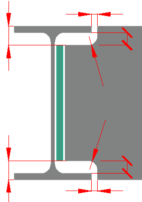
An example image created with the default, which is no body lines |
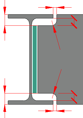
An example image created with the body lines activated. Note the better definition of the borders of the parts. |
Command : PrB_AssignLayersForDlgImage
When the command is started, it will assign these layer names to all of the parts in model space :
Plates, Endplates, Profiles, Bolts, Bolt Patterns, Dimensions
The goal is to use this command right after inserting a new macro, so that the parts will all immediatly have the default colors of you image creation dwg file.
Command : PrB_ZoomViewportHeightToFixedPixel
Use this command to create BMP files of viewports with reliable/exact pixel sizes.
Before creating your image, decide the hieght of the image that you are going to create.
Then start this command, select the viewport, and choose the amount of pixels.
You can now double-click the viewport and use the EXPORT command to write a bitmap file. The bitmap height will have the amount of pixels that you have chosen.
The number of pixels are stored in the viewport so the next time that you start the command it will show the previous pixel count.
This is also practicable for when you need to do later changes to the image. Existing controls on the image will still be in the correct position if you start this command right before writing the BMP file.