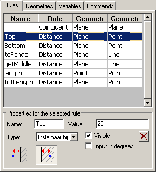
This tab contains a list with an overview of all geometrical rules in the chosen module.
One line in the list presents one rule. The list contains 3 columns. The first column is the type of rule. The second and third column describes the sub geometries of that rule.
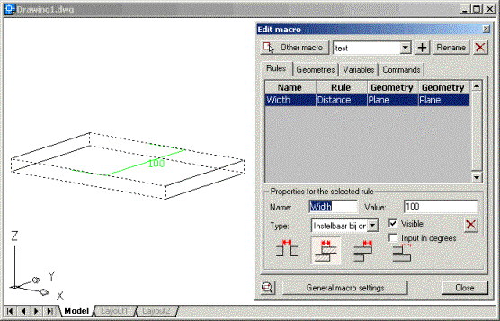
If you select a rule in the list two things will happen:
• Below the list, all options of the rule are shown such as dimension name, value,…
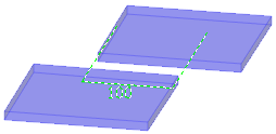
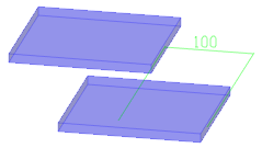
• In the drawing itself the geometries of the rule will be indicated with dashed lines. In the example shown below we see that two planes of the plate in a rule defines the width of the plate.
The properties of rules
The first four properties are only available for dimensions.
Dimension name: We use the name as a unique recognition of the dimension in the module. The name must contain at least one character. The name can contain numbers as long as the first character is not a number. A name can only be used once by one dimension within the module.
Visible: This makes the dimension visible in the Revise macro dialog box. You can hide dimensions that contain comparisons and thus cannot be modified. It can also be useful that one can see the value of a dimension without it being adaptable. You can create a dimension with the only purpose of it to view the value of that dimension: for value of the dimension you give a number (no comparison) and you set the type as flexible.
X: With this button you can remove the selected rule.
Value: This can be an ordinary number, a dimension name or a comparison. You can enter a comparison, for example “Length1+Length2”.
You can use the following symbols to make comparisons:
• +-/*: To add up, deduct, divide and multiply.
• sin () cos () tan (): Calculates the sine/cos/tangent of the value that stands between the brackets. The value between the brackets can itself be a variable or comparison.
• () ^2: Power of 2.
• sqrt (): The square root.
Type: The type determines the flexibility of the value of the dimension:
• Adjustable at design: The value of the dimension is a number and can be modified during the use of the macro (the dimension will be adjustable in the Revise macro dialog box!).
• Fixed value: the value must be a number. This value is not adjustable afterwards during the use of the macro.
• Flexible value: You must use this if other dimensions can influence the value of the dimension. If you enter for example an equation then this option must be used (this is generally already done automatically for you).
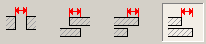
Directions of rules
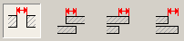
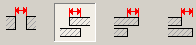
As last property you must select one of the images mentioned below.
The images depend on both the type of rule and on the sub geometries.
The image that you select indicates the context in which the rule must be interpreted.
We clarify using some examples:
We will see some scenarios of a dimension between two planes of different plates:
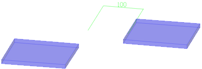
Here we’ve chosen an empty space between the plates.
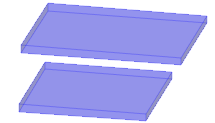
Here we let the elements flow in each other over a distance.
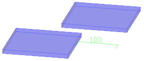
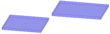
The one plate is put here beyond the other. Which plate is put beyond which plate depends on the order in which the sub geometries were selected during creation of the rule.
Again one plate is put beyond the other but the roles are switched.

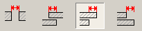
This is the coincident rule. In this case we put the two right planes on each other with the “body” of the plates in the same direction.

The planes in the middle become placed on each other with their body in opposed direction.
There are other situations possible such as distance between plane and line, cylinder and line,… but the functioning is always similar.