Parabuild objects can be stretched in two ways, both of which are described below.
1) the AutoCAD Grips
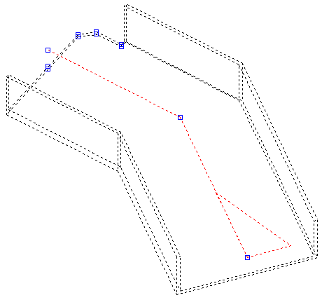
If the GRIPS variable is set to ‘1’ and an element is selected a number of small squares will appear on the element.
Bolts only have two small squares and will only allow the bolt to be moved. Plates have a small square on each of its corners. Profiles always have a small square at the start and at the end of the axis allowing the profile to be lengthened. In addition, profiles also have small squares at certain corners of cuts enabling the cuts to be edited. Curved profiles also have small squares on the axis at the place of bending and curving to alter the curve or the bend of a profile. Using the left-hand mouse button, click on a square and move the mouse, this will stretch the element. Click again on the left-hand mouse button and the modification will be applied.

The profile illustrated has small squares or grips at the start, at the end and in the middle at the place of its bend. It has various others at the cuts.
2) The Stretch command
This command can be started by typing Stretch on the command line or by selecting Modify > Stretch in the toolbar at the top.
This command allows multiple profiles to be stretched at the same time.
When the command is started, you first have to select all the elements you want to stretch in a window. This is the most important step, because it not only determines what has to be stretched, but also the location where all the elements will be stretched.
This is clarified in the following illustrations:

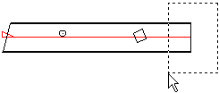
Selection of only the right-hand end of the profile.

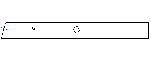
Result after stretching with the selection of only the right-hand end of the profile.

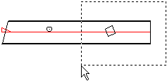
Selection of the right-hand end including the square cut in the profile.

Result after stretching the right-hand end including the square cut in the profile.
The two examples show that the lines of the window determine the stretching line. This is the point at which the profile will be stretched. The holes and cut-outs within the window are also moved during the stretching procedure, the holes and the cut-outs outside of the window remain unchanged.
Slanting profiles can also be stretched using this command, or profiles that are vertical can be stretched while remaining vertical. This is controlled by the two points that are requested after the selection of the profiles.
Stretching occurs in relation to the current UCS. This is only effective when working on a sloping UCS: Stretching with the UCS in World often gives different results for the end cuts of profiles compared with stretching using a sloping UCS.
Remember in certain situations (especially with a sloping stretch) after stretching, the connections may no longer be correct, because the current connections do not anticipate being stretched. This can be solved by editing the connections afterwards and clicking on the button ‘Reset’.