New view arrangement options
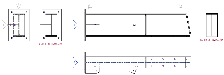
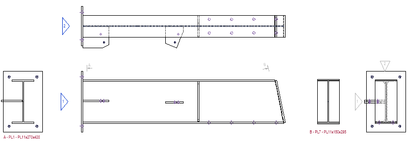
The arrangements of the views on the shop drawings are much more adjustable now.
For example :
- Strictly follow the First/Third angle projection
- Choice of front and X direction by cardinal directions (North/East/South/West)
- The member’s axis in the 2D view can be aligned with its relation to the 3D model Z-Axis. For example a column can be placed vertical on the page
Improvements in shop drawings and GA drawings
Automated dimensions on shop and GA drawings have improved :
- Improved removal of double dimensions on shop drawings
- When multiple holes are aligned the dimension lines are optionally extended to all the aligned holes.
- New options for automatic dimensioning of assembly drawings
- The time to generate workshop drawings has been reduced.
- Parabuild can now automatically draw dimensions on GA views.
- Annotations on the GA drawings are now drawn closer to the annotated parts.
They were sometimes drawn too far away before, especially for bracings.
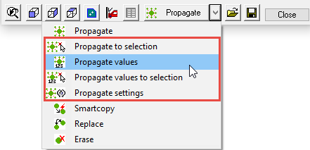
Propagate to selection
Works the same as the normal propagate, but it will only propagate to a selection of profiles, instead of the entire drawing.
Propagate values
This command will not propagate any geometry. Instead it will only propagate the sizes of the connection that is currently being edited.
The sizes will be copied to the macros of the same type, and with roughly the same base geometrics.
Stair stringers
Watch the stairs & railings tutorial here
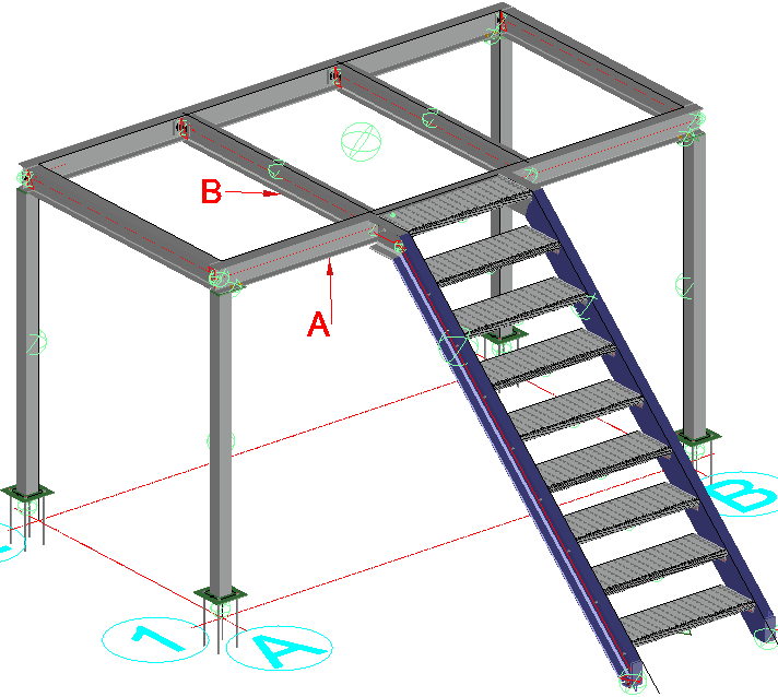
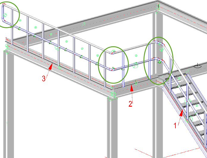
There are now 3 methods of drawing a stair in Parabuild :
- Stair from top beam to ground floor (wcs) – see image
- Stair from top beam to bottom beam
- Stair on a line
Railing
Watch the stairs & railings tutorial here
Railings can be drawn on top of an individual line, or on top of the edge of a beam.
Drawing Grating and Floor plates
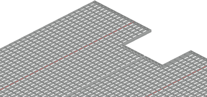
Floors are accessed by the Select profile dialog, of which there are 4 options:
- Press-lock bar grating
- Welded-bar grating
- Swage-lock bar grating
- Raised-pattern floor plates
Draw grating on a wider surface area
It is also possible to draw multiple grating panels over a wider surface area by selecting 4 beams.
Wraparound for pipes
It is now possible to automatically generate the wraparound for all pipes in the drawing. The wraparound result can be optionally shortened.

Standard parts library
You can now create one or more library drawings that contain pre-made “off the shelf” parts.
When parts in your project match a part in the standard library drawings, then the standard part’s numbers and other properties will be copied to the matching parts in your project.
This way it is clear that the part can be taken from the stock instead of having to be produced again.
Ifc and CIS/2 Import and Export
- It is now possible to import and export CIS/2 files
- There was a review step added to Ifc and CIS/2 Import so that you can compare the import model to the current 3D model.
- An import of an Ifc or CIS/2 file can now be incremental : if the source file has unique identifiers (GUIDS) then subsequent imports will update existing parts in the drawing instead of only creating new parts.
Other improvements
- New command for the conversion of plates <-> strips
- It is now possible to add Surface Treatments to any surface
- Several new properties for plates, profiles, bolts and views
- It is now possible to change the clashing settings in the bolt assemblies themselves. In previous versions this was set only once for all bolt assemblies.
- You can now configure and store the PDF printer options.
- Opening a 3D drawing will be much faster now. The speed while working on the 3D model has also improved.
- The profile sections library has been improved and expanded. These changes are fully available with a new installation, but only limited available when you perform an update.
- When converting 3D Solids to profiles with the Bimify command, the section names are now automatically mapped to section names in the Parabuild library. This tool is only available in BricsCAD BIM.
- Parabuild is now also compatible with BricsCAD V19
Generate step file of all parts for CNC manufacturing
This tool will generate a step file for each position number in the drawing.
This command will only work in BricsCAD and when the Communicator module is installed and licensed.
Pronest compatibility
A ProNest PNL Job file is always generated automatically whenever dxf files are generated.
Read the full release notes and help here
