Structural steel detailing usually involves models with many parts, which requires producing a lot of drawings and documents so the faster the better. For modeling structural steel it is important to be able to create a wide variety of structure types quickly and accurately, and when revisions are required the model should be easily adaptable.
Parabuild is designed for ease of use, flexibility and efficiency which greatly helps you meet these challenges. Short training times help you be productive sooner, and flexibility and adaptability ensures you can finish more projects quicker without sacrificing accuracy.
We aim to make steel detailing in 3D as easy and efficient as possible so that you can focus your talents on the construction projects themselves, not on the software.
These are some of the unique characteristics of Parabuild:
Short learning curve
Due to visual input, high degree of automation, instant feedback and intuitive design Parabuild needs only a short training period so the steel detailer can become productive quickly. Our experience is that 2 full days of training is sufficient for learning Parabuild if you are familiar with AutoCAD or BricsCAD. Those experienced with 3D CAD software can often learn Parabuild on their own without assisted training.
Intuitive
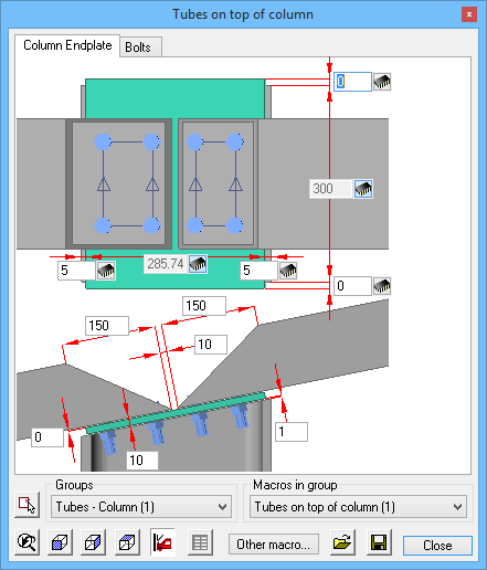
Modeling structures should be straightforward and fast, so we have put a lot of effort into making the interface and dialog boxes self explanatory. Dialogs and commands are highly visual which helps you find your way quicker.
Instant visual feedback
Whenever possible the 3D model will be instantly updated to reflect any change made by the detailer. No more guesswork – changes are immediately visible in the drawing helping you avoid mistakes and become more efficient.
Responsive 3D model
The grid, frame, connections, parts and bolts are all linked up and adapt when when needed. When the grid is changed, the frame will adapt and when the frame changes the connections will adapt. This results not only in productivity gains during revisions, but presents opportunities for re-using some regularly drawn building components.
Runtime exercises
To make it even easier for you to learn Parabuild, we have designed step by step exercises that are shown on-screen. This way learning Parabuild on your own is fun to do.
Customization without programming
The standard connections and macros in Parabuild are all fully defined using geometric constraints in template drawings. This means it is possible to modify existing connections or add any new custom connection without hiring a programmer or writing any code.
Learn more about Geometric Constraints
Powerful connection and macro system
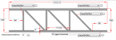
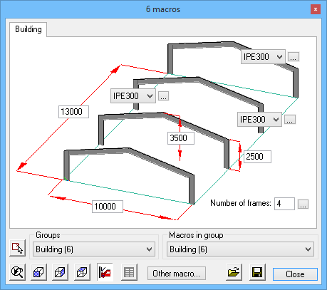
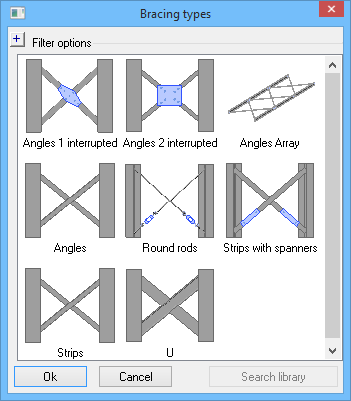
Not only is the expansive standard connection library convenient and easy to use, every single one is created using tools that are available to all drafters without requiring the programming of a single line of code. Every standard and user connection resides in a template drawing which means the drafter can adapt it to his own needs. Parabuild is the only structural software that allows the user to define any type of connection without programming. Newly made connections are entirely integrated with the existing connection system for easy re-use in all your projects. Macros are built up in the same template-based way as connections and can compose of any number of members, connections, dynamic arrays and sub-macros. Examples of provided standard macros are bracing, trusses, purlins, cage ladders, etc…
Fast and easy 3D modeling
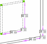
Designed specifically for the construction industry, the Context Modeler helps rapidly and accurately drawing frame elements and sub-parts, all linked and responsive to changes of linked elements. The interface could not be more self explanatory: tell Parabuild what you need in simple terms, and point to the location where you need it. Parabuild will draw a temporary element dependent on the cursor location and the construction elements near the cursor. Move around the cursor and different solutions are proposed, with magnet-like snapping to edges or middle points. The result is new geometry that was automatically linked with base geometries using geometric constraints. The big advantage is that you can model directly in 3D without cumbersome intermediate steps, and still end up with a completely linked model.
Learn more about the Context Modeler
Completely integrated in AutoCAD & BricsCAD
Most drafters are already familiar with AutoCAD, and BricsCAD works the same way, which reduces training investment. Parabuild’s structural objects can be modified through the standard commands or using the Object Property Manager, all Parabuild objects are integrated as if they are native AutoCAD/BricsCAD objects.
Learn more about AutoCAD and BricsCAD
![]()

Avoid mistakes
When the 3D model contains all the building information, the potential for mistakes is greatly reduced. The visual representation serves as a check by itself, and there are multiple tools to aid in checking the drawing such as clash control and bolt clearance checks. Bills of Material and workshop drawings are automatically generated from the model ensuring your dimensions, counts and numbers match the structure.
Automatic output
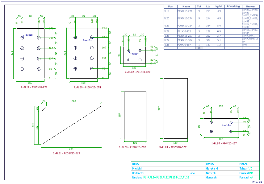
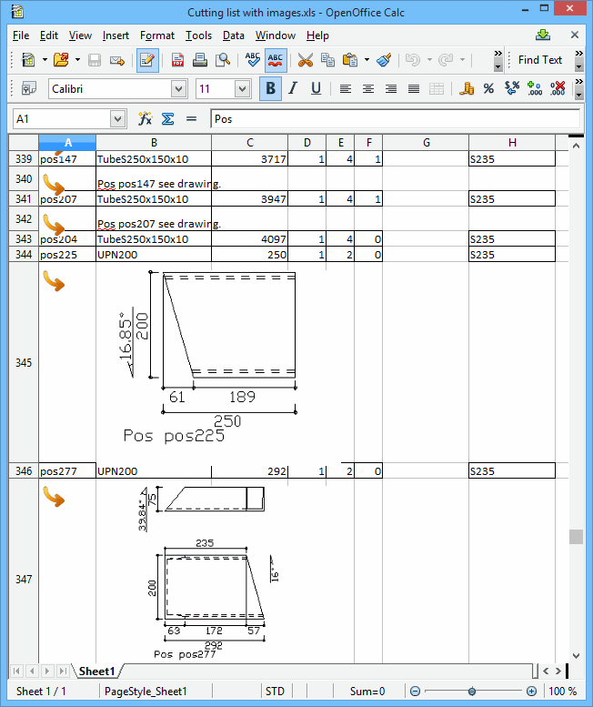
Generate CNC files, IFC, BOMs and workshop drawings automatically.
Estimating, bidding and sales
Because creating a preliminary model can be done quickly, it is a useful tool for your sales team. Use preliminary models for estimating (counts, weights, paintsurface, …) and support the bids you make, but also use the virtual 3D models to impress during your sales efforts.

