Draw welds
The Context Modeler has a button  that allows you to quickly draw a weld with a single mouse-click
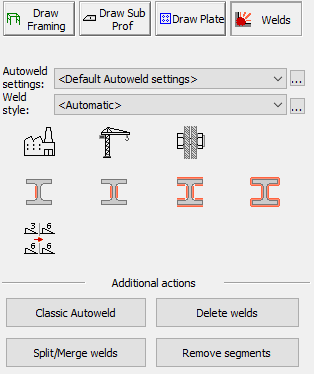
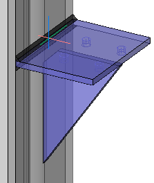
After selecting the Welds options in the context modeler, one only needs to point the cursor to a joint.
The context modeler will show the weld that could be drawn at that location.
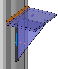
By clicking on the left-mouse button, the weld will be drawn.
|
|
As you move the mouse around, welds are proposed at that location. |
The resulting weld after clicking the left mouse-button. New welds will be put on the Welds layer, which is orange by default. |
Disclaimer
Welds created automatically will get sizes that may not sufficiently account for loads and stresses. All welds should be checked versus engineer specifications.
Influencing what welds are proposed
There are several options in the dialog that determine which weld is drawn by the context modeler :
- AutoWeld settings - Choose which AutoWeld settings should be used for the welds drawn by context modeler
The context modeler uses the same technique as the AutoWeld to determine the weld type and size that should be drawn at any given location.
Use any of the following options to choose a different AutoWeld configuration : - <Default AutoWeld settings> - The default AutoWeld settings that are loaded when Parabuild starts are used. The default AutoWeld settings can be stored in the AutoWeld settings dialog box
- All of the saved AutoWeld settings files - All of the previously saved AutoWeld settings are listed here. You can choose one of them here and also use the
 button to edit the settings file directly. The AutoWeld settings can be saved in the AutoWeld settings dialog box.
 - <Add new AutoWeld settings file> - By choosing this option, you can create a new AutoWeld settings file from scratch.
- Weld style - Choose the weld style that should be used for the welds drawn by context modeler.
The following options are available : - <Automatic> - When this option is active, the weld style is chosen automatically based on the rules in the chosen AutoWeld settings.
- All of the saved Weld tag style settings files - All of the previously saved weld tag styles are listed here. You can choose one of them here and also use the button to edit the settings file directly. The Weld tag style can be saved in the Weld Symbol dialog box.
- <Add new weld tag> - By choosing this option, you can create a new Weld tag settings file from scratch.
 Allow shop welds - When enabled, welds between elements that are in the same assembly can be created
 Allow field welds - When enabled, welds between elements that are not in the same assembly can be created
 Allow bolted parts - When enabled, welds between elements that are already bolted against each other can be created
 Only draw a single weld segment - When enabled, only welds with a single segment can be created
 Draw on the opposite plate-side too - When enabled, then the weld on the opposite side of the plate can also be created (if it is found)
 Draw multiple segments - When enabled, all the valid segments between the same 2 parts can be created (consistent with the chosen AutoWeld settings).
 Draw all-around welds - When enabled, an all-around weld can be created for the same contact surface (The resulting weld may not be fully all-around if the geometry does not allow it)
 Unify weld sizes - When enabled and multiple welds can be created with one click, then all of the segments will get the same weld size
Additional actions
The following buttons do not influence the context modeler behavior, but were added here for your convenience :
- Classic AutoWeld - Opens the AutoWeld command that allows you to draw welds automatically on a selection of parts or on the entire drawing
- Delete welds - The Delete welds command allows you to delete a selection of welds
- Split / Merge welds - The Split/Merge welds command allows you to split or merge the weld segments of welds
- Remove segments - The Remove weld segment command allows you to remove certain segments of a weld