Various commands without icons
The commands listed below do not have an icon associated with them.
Their usefulness is often too limited to allow them to take up space in the standard Parabuild ribbon and toolbars.
Command : PrB_Menu
When you enter this command, all of the Parabuild ribbons and toolbars will be unloaded and loaded again.
This can be a useful command when no Parabuild icons are loaded, when a part of them are missing, or when the icons do not show properly.
Command : PrB_IconColorsOverride
Normally, Parabuild will automatically show dark icons when light theme is active, and light icons when dark theme is active.
The color theme can be set with the COLORTHEME variable.
This command allows you to override the Parabuild icons to dark or light, regardless of the current color theme of AutoCAD/BricsCAD.
Command : PrB_GetCenterOfGravity
This command can work on a single or on multiple parts.
It will draw a plane object at the center of gravity location of all the selected parts combined.
Command : PrB_CutCommandsCreatesMacros
This is actually a variable that enables the creation of macros during various Parabuild cutting/coping commands.
The advantage of enabling this is the fact that the cuts will be updated automatically whenever one of the profiles change.
The default value is to enable the automatic creation of macros.
The following commands apply to this variable : Cut against an Element (shorten only), Cut End against an Element (shorten and extend), and Miter cuts.
Command : PrB_ConvertLinearSolidsToProfiles
This command only works in BricsCAD when the BIM module is licensed.
The purpose of it is to convert general 3D Solids into Parabuild profiles.
To use it, you should follow the following procedure :
- Open a drawing that contains 3D Solids (the solids could have been imported from a STEP file)
- Start the BricsCAD BIMIFY command. This will analyze the solids and store profile section information in the solids.
- Start the PrB_ConvertLinearSolidsToProfiles command. This will create a new profile on top of each solid that has section information.
- Use the Visibility Manager to switch between LOD visibility modes, because we now have multiple objects on top of each other.
This is solved by assigning all the 3D Solids as LOD200 objects.
All Parabuild objects are considered as LOD400 objects.
Command : PrB_CacheMacrosFromLibrary
This command will load all of the Parabuild macros in the library into memory.
After using this command, all the commands for inserting new connections will now respond faster than usual.
(normally, the macros need to be loaded into memory the first time that you start a certain connection command)
This command's effect will be lost when you close Parabuild.
Command : PrB_DrawBoltsOnHoles
You can use this command to automatically draw bolts on all holes in the selected parts.
This can be useful when you have parts with a lot of holes but the bolts were deleted.
Command : PrB_EraseAllHoles
This command will erase all holes in the selected parts.
Command : PrB_EraseAllCuts
This command will erase all of the end-cuts and all other cuts that reside in the selected parts.
Command : PrB_CheckPunchHolesVsThickness
Some hole punching tools shouldn't be used when the hole diameter that needs to be punched is smaller than the plate thickness.
This command will loop the entire drawing and search for such plates with small holes.
It prompts the part number when such a plate is detected.
Command : PrB_CreateAcisBody
This command will create a 3D Solid copy of the selected part. The solid is drawn exactly on top of the Parabuild part.
Command : PrB_DefaultStockLength
This command allows you to change the default length of all stock items listed in the Profile Length Optimization command.
Command : PrB_SetViewLimitation
This command refers to the 2D front/back view limitation shown in the Visibility Manager. By allowing you to change these values through the command line, scripts, icons or tablets can also change these values.
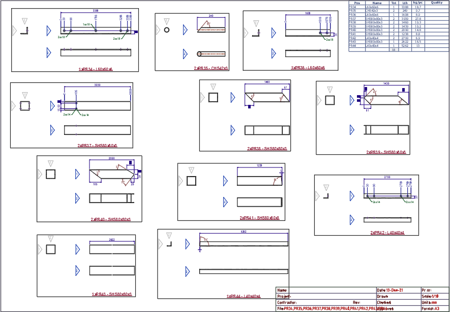
Command : PrB_AddFramesAroundViewsInSheets
This command will draw a frame around each set of views that belong together in the workshop drawings.
This may be useful on gather sheets, when the workshop drawings contain a lot of views.
Command : PrB_BillTableSettings
This command allows you to change the bill settings when you've opened a bill template drawing.
More information about the bill templates can be found in the Settings for page and layout topic.
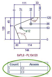
Command : PrB_InsertQuantityBill
This command is meant to be used in the single part shop drawings.
Therefore you should start it when a plate or profile shop drawing is already open.
Then it will draw a quantity bill for each part on the drawing (it asks you for the location for the bill for each part).
The bill contains a list of all the assemblies where the part is being used, and also the amount of parts used by those assemblies.
The bill that is inserted is located here : \Parabuild\Pb_Lib\Workshop drawings\Bill Templates\QuantityOnAssemblyBill.dwg
Command : PrB_ShowHistoryBlocks
This command can create a block reference of the position or assembly history block.
It allows you to see what has been stored in the history block. It is used primarily for debugging.
